Terri
Meyer Boake, BES, BArch, MArch, LEED AP |
|
Arch
173:
|
last updated
March 6, 2022 10:34 AM
Project Description:Each week you are assigned a "sketch" to complete, as described below. These are to be submitted to LEARN the following week by 9am - prior to the start of class. Freehand sketching is essential to the development of projects and construction details. Ideas are explored before they become part of a digital construction drawing set. Being able to sketch approximately "to scale" is key to making sure that details work and respond to material sizes. Lettering must be neat and conform to standard architectural lettering styles that have long been done "by hand". When a computer is not at hand and meetings are underway, there is nothing handier than sharing a roll of trace and knocking out sketches. Log-in to LEARN: here |
| DATE | DESCRIPTION OF SKETCH REQUIREMENT |
1Jan 11 |
SKETCH 1: ARCHITECTURAL LETTERING Architectural lettering has always been block style and highly consistent so that multiple people can work on a drawing set and maintain a sense of order. Clarity is critical as this is a legal document and any misinformation can result in errors. Print out the entire alphabet in block letters as well as the numbers 0 through 10, and the character & You may do this on lined paper or on a blank page where you have set out lightly drawn control lines. Create an assembly list as you were required to do for the final project for Arch 172 for the wall assembly. Print this out by hand, left adjusted, as you would put it on a drawing. You will be required to use this lettering style to label all subsequent sketch details this term. Take a photo and upload to LEARN. |
2Jan 18 |
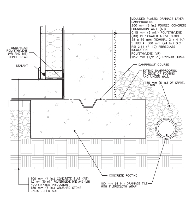
SKETCH 2: FOOTING DETAIL You are to draw this detail at HALF FULL SCALE, but with a couple of improvements. NOTE: There are many ways to approach doing this detail. For more information on foundation walls, please have a look at this article
|
3Jan 25 |
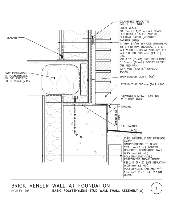
SKETCH 3: SILL DETAIL FOR BRICK TO FOUNDATION You are to draw this detail at HALF FULL SCALE, but with a couple of improvements. We need to add rigid insulation in the cavity to make the R-value of the wall better. Add 38mm XPS insulation between the air barrier and the brick, maintaining a 25mm air space between the XPS and the brick. You will need to increase the dimension of the concrete foundation to make this work. It is drawn at 200mm and needs to be 250mm. Instead of the bitumenous building paper we are going to use a high quality air barrier material (like Tyvek). We can now omit the polyethylene vapour barrier that is normally placed behind the gypsum board. Will explain why later. Everything else can stay the same. This is to be hand drawn. Please use differentiated line weights and label the detail as below WITH ONLY THE METRIC UNITS using your best architectural lettering.
|
4Feb 1 |
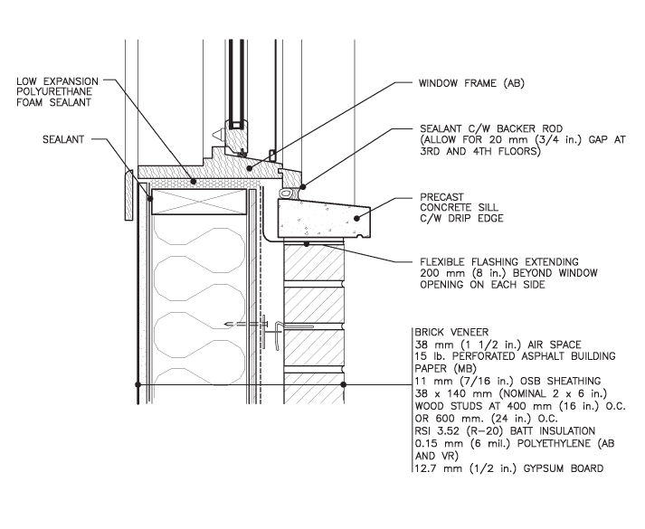
SKETCH 4: WINDOW SILL IN BRICK WALL You are to draw this detail at HALF FULL SCALE, but with a couple of improvements. We need to add rigid insulation in the cavity to make the R-value of the wall better. Add 38mm XPS insulation between the air barrier and the brick, maintaining a 25mm air space between the XPS and the brick. This increases the space between the back of the brick and the wood frame wall. The window must cover this gap. Keep the alignment of the window on the precast concrete sill the same and the overall depth of the window the same. Windows are purchased at fixed sizes. Now you need to add a nice wood window sill/casing on the interior to complete the detail. Now that we have added the cavity insulation, we can eliminate the poly vapour barrier on the interior. Labels only in metric please.
|
5Feb 8 |
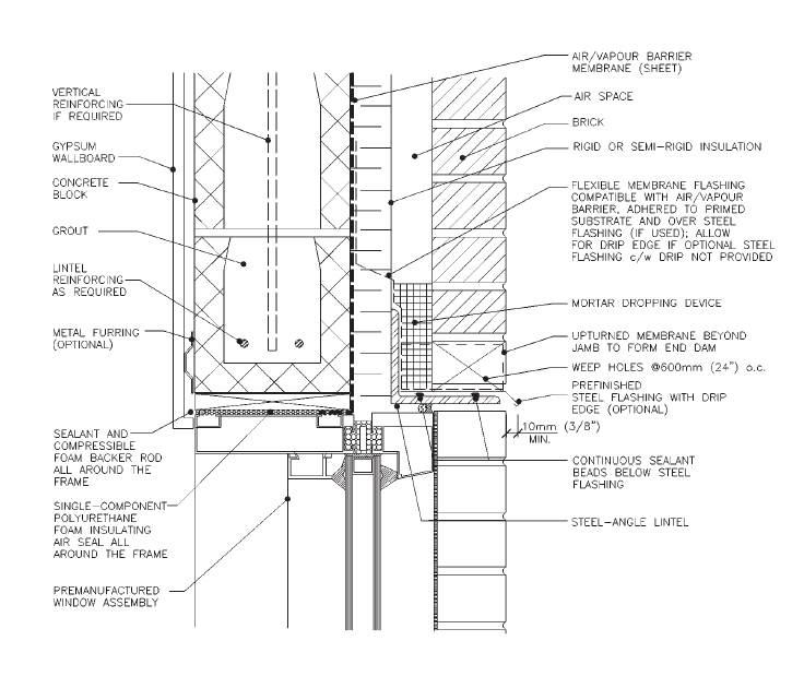
SKETCH 5: WINDOW HEAD DETAIL For our window head detail we are LOOKING AT a concrete block structural wall with brick veneer but you are being asked to replace the concrete block with a light frame wood wall. That wood frame wall will be constructed from 38x140 studs and have 140mm of batt type insulation inside. The wall will have gypsum board as its interior finish. There will be 13mm OSB and a spunbonded olefin air barrier between the studs and the cavity insulation. Be sure to show the lintels over the window. These will be a pair of 38x184 lintels. Make sure that you place insulation between them. Maintain a 25mm shim space between the lintels and the window frame. That gap gets filled with sprayfoam insulation once the window is fixed into position. The cavity insulation is 50mm thick. Air space is 25mm. The brick part of the detail as shown below is more or less ok as is. The steel angle is just spanning across the opening, bearing on each side of the opening on the adjacent brick veneer walls. It is NOT attached back to the wood framing. Please have a look at the sketch I posted on Teams in the Q&A as people seem to have a hard time figuring out the swap of the CMU for wood framing.
|
6Feb 15 |
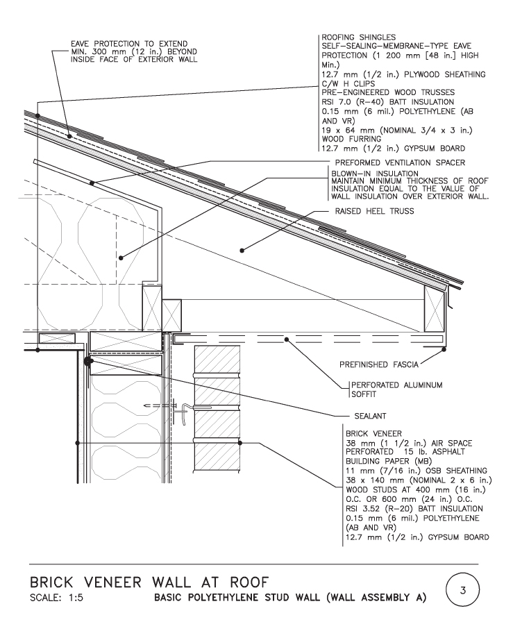
SKETCH 6: SOFFIT (due March 1) Please read carefully as this detail is looking to correct quite a few errors that were made on this part of the wall section from last term. TO BE DRAWN AT HALF FULL SCALE. Pictured here is a wood truss. You are going to replace the wood truss with a rafter. The rafter has to have a notch that allows it to sit on the ceiling joist header. Make the ceiling joists 38x286 so that they are deeper to accommodate 300mm of fiberglass batt insulation. Eliminate the 19x64 furring that is shown on the underside of the trusses. When you are using regular ceiling joists there is no need for these. They screw the gypsum board directly to the joists. Also, we are adding 38mm of XPS insulation in the cavity as per some of the previous details above. Use spunbonded olefin air barrier material instead of the asphalt building paper. Add a rain gutter/eavestrough. These are around 100mm deep and 150 mm wide.
|
8Feb 22 |
No class - Reading Week |
7Mar 1 |
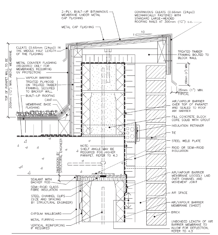
SKETCH 7: PARAPET To be drawn at half full scale. This one can just be copied without any changes. Try to understand well what exactly you are drawing, the construction sequence and the ability to make the insulation and the air barrier continuous. You can simplify the notes.
|
9Mar 8 |
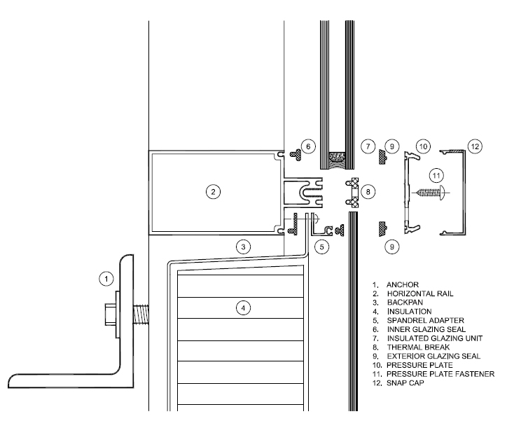
SKETCH 8: CURTAIN WALL The last part of the term focuses on facade and cladding systems. The next 3 sketches are about the details of curtain wall. They are all uploaded now so that you can pace your own work for the remainder of the term. No changes to the detail that is posted, just try to understand how this system goes together. There is no scale assigned to this image, but the rectangular part of the aluminum curtain wall section is approximately 125mm deep and 50mm wide. Draw this at 1:1 scale. This one is a vertical section view and the steel angle is used to connect the vertical mullion to the floor slab edge.
|
10Mar 15 |
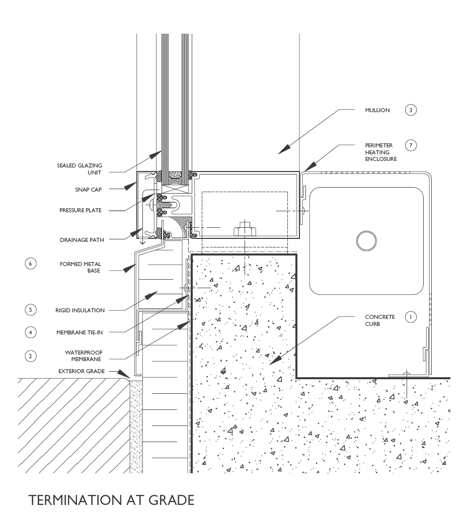
SKETCH 9: CURTAIN WALL BASE CONDITION This next view of the curtain wall system is its connection at the base of the wall. Curtain wall is applied as a rather expansive system, usually used to clad large buildings where this forms a continuous skin across the facade. Same scale to be applied as the detail above, draw at 1:1, no changes.
|
11Mar 22 |
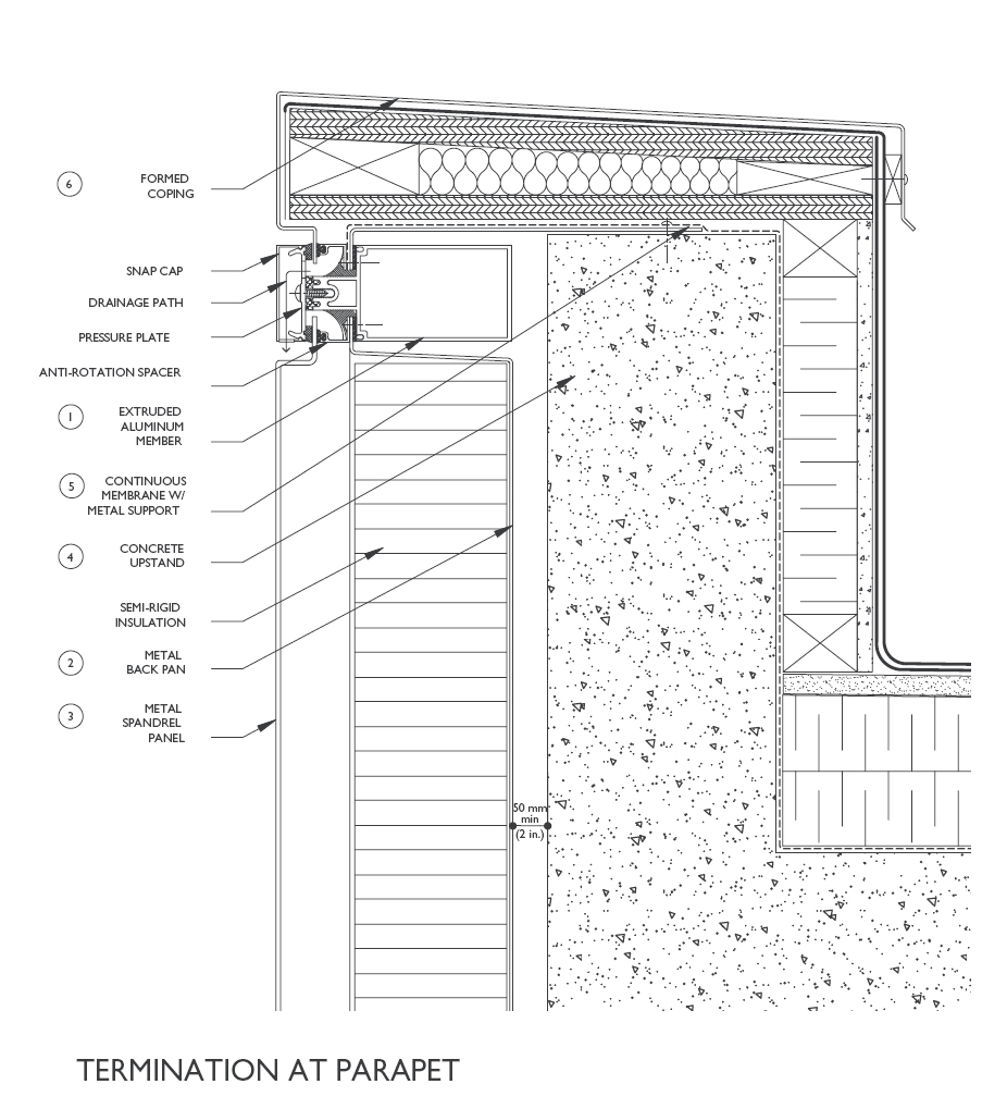
SKETCH 10: CURTAIN WALL PARAPET CONDITION This next detail looks at the termination of the curtain wall at the roof of a building that has a flat roof and parapet, which is pretty typical for most tall buildings. Note that the parapet top slopes towards the interior to prevent staining of the facade. There is an attempt made at continuity of insulation. Again same scale, draw at 1:1, no changes.
|
12Mar 29 |
|
| No sketch or notes assignment for this week. |
Evaluation: |
DETAIL SKETCHES: 10 @ 4% = 40% Late Penalties: Only in the case of a justified medical or personal reason will these penalties be waived, and only if these have been officially submitted to the Undergraduate Student Services Co-Ordinator and accepted by the Undergraduate Office. Students seeking accommodations due to COVID-19, are to follow Covid-19-related accommodations as outlined by the university here: (https://uwaterloo.ca/coronavirus/academic-information#accommodations). |
last updated March 6, 2022 10:34 AM