Ontario College of Art and Design
Addition
Sharpe Centre for Design
Alsop
Architects with
Robbie/Young + Wright Architects
Toronto, Ontario
| Terri Meyer Boake BES BArch MArch LEED AP Associate Professor :: Associate Director :: School of Architecture :: University of Waterloo |
|
Alsop
Architects with Toronto, Ontario
|
| Project Information: |
In November 2000, OCAD selected European firm Alsop Architects as design architect to work in a joint venture with Toronto-based Robbie/Young + Wright, the project architect, to produce OCAD's capital expansion project. Ontario College of Art & Design (OCAD) broke ground in late 2002 in preparation for its $42.5 million expansion and renovation featuring the Sharp Centre for Design (SCD). By March 2003, foundations were in place and construction upwards began. The SCD was completed in Winter 2004. All new and
renovated space was complete by August 2004. The official opening
of the SCD, and the new and improved OCAD occurred in October
2004. The
Team: |
Project
Images: |
|
construction
sequence movie 1 link |
construction
sequence movie 2 link |
|
|
|
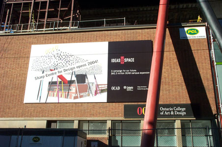
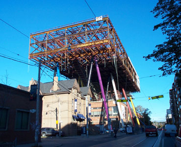
Architect's
rendering of the project.
|
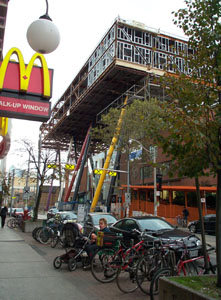
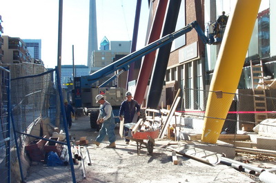
View
looking south on McCaul Street.
|
|
|
|
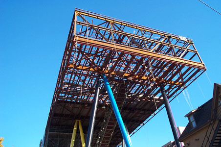
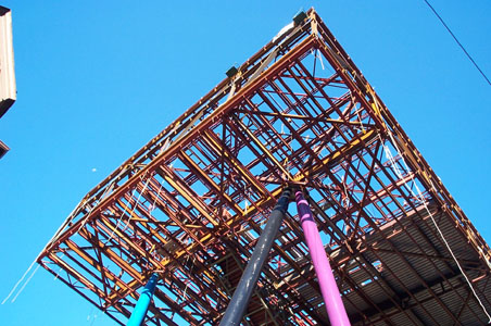
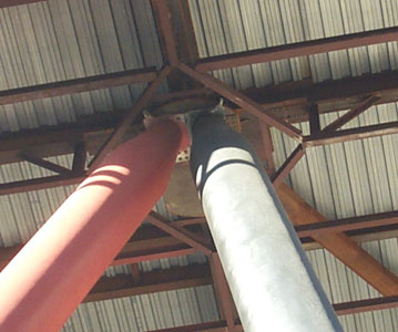
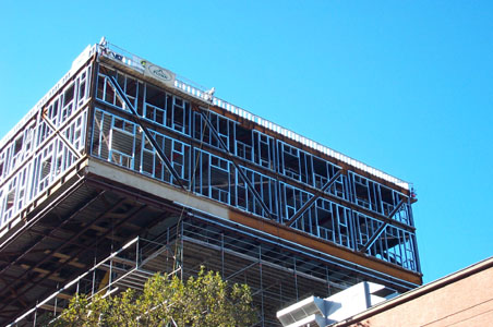
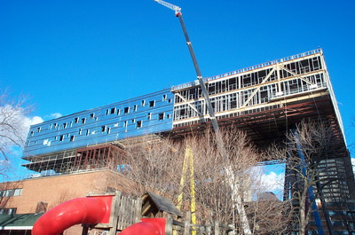
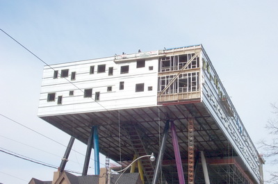
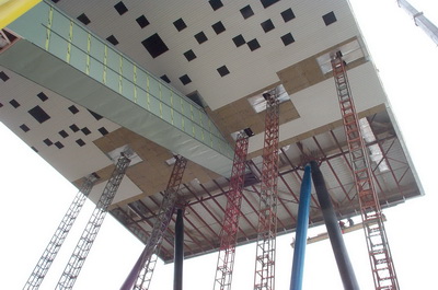
The
large steel truss box sits atop hollow structural steel legs of approximately
93 feet (27m) in length and 914mm in diameter. The thickness of the section
wall is 25mm. The taper at each end is 2.5m.
|
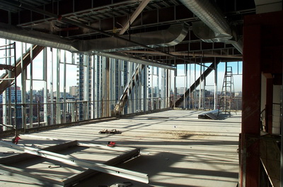
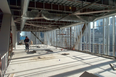
There
will be two floors of classroom space in the addition. The overall dimensions
of the floor plate are 30m x 83m.
|
|
|
|
| October
17: the installation of the steel decking for the floors is in progress.
|
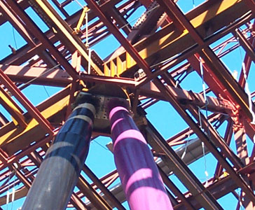
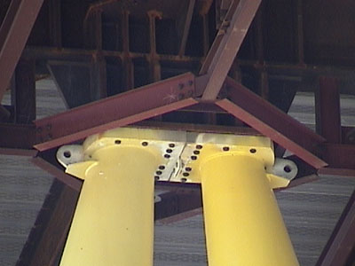
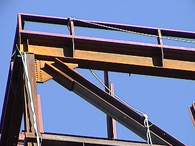
Detail
showing the connection of the steel leg supports to the base plane of
the trussed box.
|
 |
 |
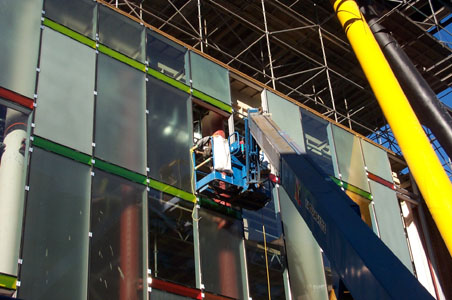
Glazers
installing the sealed units in the colourful curtain wall at the base
of the building.
|
Detail
of a support connection for a double leg attachment.
|
 |
 |
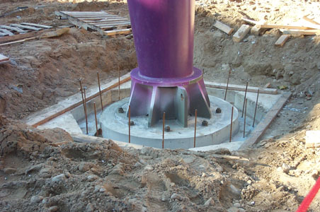
Base
connection detail prior to being encased in concrete. Each pair of "legs"
is attached to 3 caissons that are tied together below grade to absorb/prevent
displacement/lateral movement being transferred from the building through
to the foundation.
|
Base
connection detail for the steel supports. The steel connection is covered
in concrete.
|
 |
 |
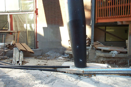
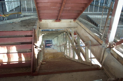
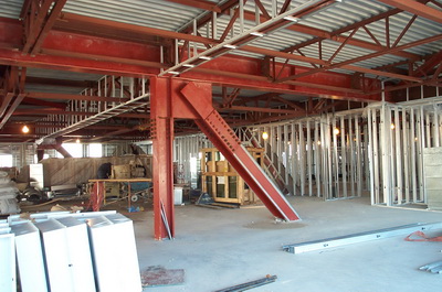
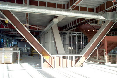
A
primary means of
fire egress for the addition is via an exit stair that flies through
the space beneath the box and the plaza below. Click image for close
up detail.
|
Connection
detail for column supports -- before and after fireproofing.
|
 |
 |
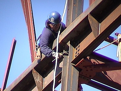
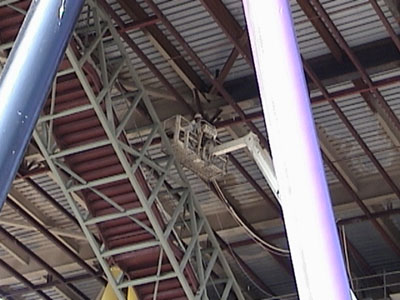
Iron
workers atop the steel box... watch
him work!
|
Iron
worker installing bolts in the steel frame. This worker is perched on
a steel frame that floats 8 floors above the ground below... watch
him work!
|
 |
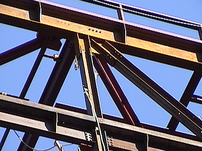 |
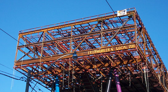
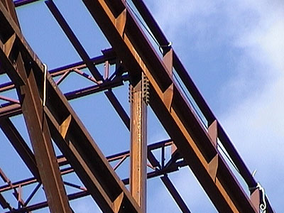
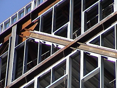
Connection
details at the top level of the box.
|
Connection
details of the steel framed box.
|
 |
 |
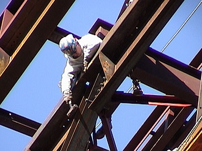
Grinding
operations underway. Click image for close up detail.
watch him work! |
Steel
connection at the corner of the box. Most of the connections are reinforced
for moment resistance.
|
 |
 |
In
preparation for the attachment of cladding systems, a cold rolled steel
stud framework is installed between the truss members.
|
This
framework is fitted around the structural members. The location of glazed
window panels must be coordinated with the structure and placement of
diagonals.
|
 |
 |
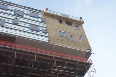
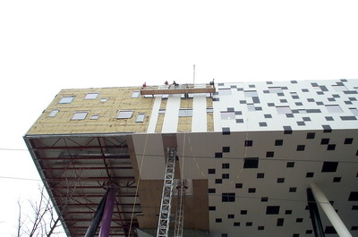
The
substructure for the exterior wall cladding system is being installed
at the north side of the building at the beginning of November 2003.
|
Spray
on fireproofing is being applied to the hidden portions of the steel structural
system.
|
 |
 |
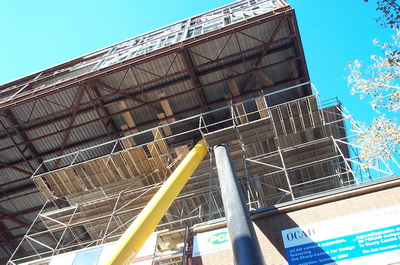
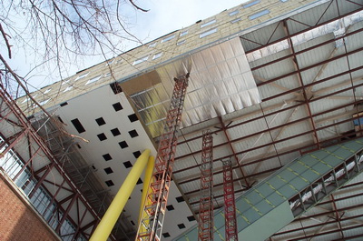
Scaffolding provides a working platform to commence skinning the underside
of the tabletop. |
Work proceeds at the front entrance on McCaul Street. |
 |
 |
The underlayer of the cold formed steel cladding is installed. |
South end of the table top with most of the exterior under layer of cladding
complete. |
 |
 |
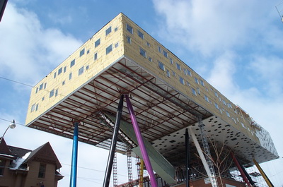
Rigid insulation is installed. |
View of the underside of the table top with cladding operations in process. |
 |
 |
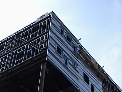
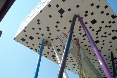
Cladding operations. |
The black squares are installed as a layer of corrugated cladding that
sits over the continuous white underlayer. |
 |
 |
Installing the metal siding. |
The cladding also covers the diagonal fire escape stair. |
 |
 |
Intumescent coating is used to fire protect some of the larger exposed
diagonal truss members. |
View across the south end of the table top prior to cladding. |
 |
 |
View across the south end of the table top prior to cladding. |
View down the diagonal fire stair. |
 |
 |
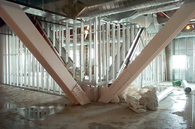
Interior view of one of the rare steel members that will be left exposed. |
Most of the steel on the interior is furred out and clad in gypsum board. |
These images are for educational use only and may not be reproduced commercially without written permission. tboake@sympatico.ca |
Updated June 18, 2008