Basic Connections
Welded Connections
Welding. Steel to be welded must be of a certain type that permits welding. A high carbon content, such as that which is found in historic cast iron, cannot be welded. Most structural steel that is used in contemporary buildings is able to be welded. This would include steel that is found in W, C and L shapes as well as Hollow Structural Sections. The steel that is used in Mechanical Pipe is different in nature and requires different welding. Carbon steel that is to be welded may not have any primer in the area that is to be welded. Small amounts of corrosion that might have occurred to the bare steel during transportation and erection will be sanded away prior to welding.
The two basic types of welds that are found in steel projects are the fillet weld and the groove weld.
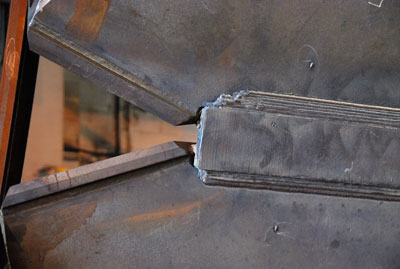
This column is prepared for welding. The edges of the upper column have been milled away to allow for the weld, providing surface area for the weld to attach the two pieces of steel. This is a variation of a V groove weld in that only one column element has been milled. Temporary tabs hold the pieces together prior to welding. |
This column to column splice is welded. Only the outside faces of the flange have been welded, and in this case, the welds ground smooth. The temporary tabs have been cut off. You can see the small protrusions of plate remaining on the column. As this structural steel will be concealed, no further remediation is required. |
Welding is used to attach these tubular members. A simple fillet weld is used to attach the smaller HSS to the larger one. The change in size provides space for the weld. |
This large steel member has been spliced with an inline weld. You can see the evidence of multiple passes through the lines in the weld material. |
This HSS to HSS connection is being prepared for welding. In this case both members have had material removed to ensure symmetry in the connection. This element is AESS. |
After multiple weld passes, excess material is ground away making for a seamless and smooth transition for this AESS member. For this design welding was the only option as bolting would not have been suitable. |
 |
|
The lifting tab on this 70 tonne truss is welded to the top flange of the truss. The fillet weld uses multiple passes to reach the required strength of the connection. If there are only two lifting points on this truss, each must be able to resist a minimum of 35 tonnes! |
Fillet welds are used to connect this steel which will ultimately be concealed on the project. A slight offset of the plate to the next element permits a simpler fillet weld to be used. |
The triangular diagrid elements on the Bow Encana are connected to each other using welding. The tabs are located on the lower side of the element and will be used to aid alignment during the lift. The reinforcing plate inside the member is set back from the face so that it can be attached by a fillet weld. |
Protection is placed around the connection in order to allow for weather protection during the welding process. As these welds must be finished to AESS4 quality, it will take some time to complete the work. The primer has been held back from the weld area. |
A closer look at the connection after a couple of weld passes have taken place. More will be necessary in order to develop full strength and fill the gap in preparation for grinding, filling and painting. |
Once the welding is complete, grinding and filling takes place. This creates signficant extra cost for the project but the smooth welds are necessary for the aesthetics of the face of the diagrid elements. |
 |
 |
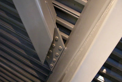
Welded connections can be used in conjunction with bolts. It is not necessary to grind welds if they are done properly. Here slight variations in dimension of the pieces to be connected permit simple fillet welds for parts of the connection. |
Not all welds need to be continuous. Here intermittent welds are more than sufficient for strength. They have been carefully aligned beside adjacent bolts for a neat appearance in this AESS project. |
