Architecturally Exposed Structural Steel
The AESS Categories - AESS 2 - Feature Elements (> 6 m)
AESS 2 – Feature Elements includes structure that is intended to be viewed at a Distance > 6 m. It is suitable for "feature" elements that will be viewed at a distance greater than six meters. The process requires basically good fabrication practices with enhanced treatment of welds, connection and fabrication details, tolerances for gaps, and copes. This type of AESS might be found in retail and architectural applications where a low to moderate cost premium in the range of 40% to 100% over the cost of Standard Structural Steel would be expected.
 |
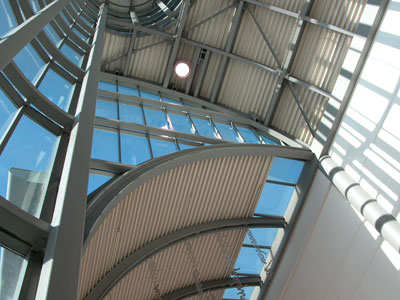 |
National Works, Vancouver B.C.: The project uses more articulated steel design predominantly with W sections. Much of the structure is located at ceiling height, so at a distance for viewing and therefore allowing for a lower level of detailing and fine finish. This structure interacts with wood, which will change aspects of its detailing and coordination during erection. |
National Trade Centre, Toronto, ON: The project makes use of relatively standard steel sections, but the design and fabrication employs a higher standard in terms of arrangement and detailing. There is some section bending required which increases fabrication costs and can impact detailing. Much of the structure is still located in excess of 6 metres above view. |
AESS 2 will generally be found in buildings where the expressed structure forms an important, integral part of the architectural design intent. The defining parameter of viewing distance greater than 6 metres will infer that you might find this sort of steel in high level roof or ceiling applications. For this reason you might be specifying AESS 2 steel for the distant components of your structure, and a higher grade of AESS for the low level elements of the structure. Just be sure that these are clearly marked on the drawing sets so that the treatments can be differentiated and the respective cost premiums separated out.
It will be more common to see W or HSS members specified for this category, rather than more industrial members such as OWSJ. This type of application may use a combination of bolted or welded connections. As the viewing distance is great, there is normally less concern about concealing the connection aspects of larger pieces to each other - hence no hidden connections.
In the case of the National Works Yard, the use of exposed steel has reduced finishes and helped in achieving a LEEDTM Gold rating. The predominant section choice is a W Shape, and the detailing has been kept fairly standard. The specialty details that support the roof structure and the parallam wood beams, remove the details from close scrutiny. The primary connection choice to join major sections is bolting, however the elements themselves have been shop welded prior to shipping. Although the steel is able to be viewed more closely from the upper floor level, a decision was made to maintain the tectonic of the W sections and bolted connections consistent, given the use of the building as a Works Yard Office. There are some specialty details added to the repertoire, centred around the support of the PV skylights and the wood structure.
 |
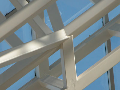 |
Edmonton City Hall: The trusses that support the pyramidal glass roof are created using square HSS sections. The viewing distance varies, but is typically greater than 6 metres, even from the upper levels. |
An up close inspection reveals many inconsistencies that are reasonable to leave "as is" due to the view distance. The extra expense to fill, grind and carefully align the members would be lost on users of the building. |
Edmonton City Hall uses square HSS members to create a very complex high level truss system to support a pyramidal skylight. The viewing distance has permitted a less fastidious level of fill and finish on the members as these are not in close range of view or touch. The structure appears to use all welded connections. For the straight run truss elements the square HSS sections align fairly cleanly. This becomes more difficult at the angled junctures of the roof. But given the pyramidal shape round HSS members were not deemed appropriate so a detailing compromise was required at the junctures - and the viewing distance made this workable.
The cost premium for AESS 2 ranges from 40 to 100%. There may be lower costs associated with the clean use of standard structural shapes with bolted or simple welded connections, and higher costs associated with the use of HSS shapes, complex geometries and a predominance of welded connections. As one of the common applications of AESS 2 will be for roof, skylight or ceiling support systems, the fire protection method must be known from the outset of the project. If intumescent coatings are used, these can help to conceal any inconsistencies in surface conditions.
AESS2 - Characteristics
AESS 2 includes Characteristics for AESS 1, and also Characteristics 2.1 to 2.4.
2.1 Visual Samples – This Characteristic is noted as an optional requirement for this and all subsequent Categories due to issues of suitability, cost and scope.
 |
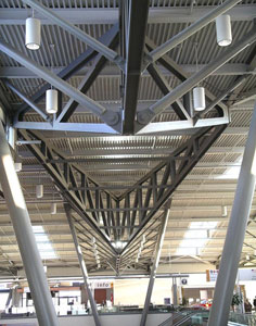 |
| A digital mock-up was done for this connection. It allowed the client to understand how the detail would look. It was an efficient method that did not slow down the process. The image above is part of the fabricators' detailing package. Fully rendered 3D models can also be used as a point of clear communication between the parties to speak more to the final finish appearance, including colour. |
Ottawa Airport: The actual piece when viewed in the finished project is very close to the predicted quality of the object. This method saves time and money for the project. |
Visual samples that might be used to validate the intention of the final installed product for AESS can take a variety of forms. Visual samples could be a 3-D rendering, a physical sample, a first off inspection, a scaled mock-up or a full-scale mock-up, as specified in Contract Documents. Visual samples could range from small pieces of fabrication that might include connections or finishes, to full-scale components.
 |
 |
A special physical mock-up was made for Pearson International Airport. Although minor modifications were made to the detailing for subsequent elements, it was incorporated into the project without any issue. |
It is simply not possible to identify the "wishbone" that was the mockup. It would have been a waste of time and money to have discarded the initial piece in favour of one that was a perfect match. |
Not all projects would benefit from the construction of large-scale mock-ups, hence making this Characteristic optional. In some cases it is suggested that an agreement to incorporate full-scale mock-ups in the final project would make practical and economic sense. Again this decision would depend on the particular job requirements. It is very important to bear in mind the potential for delay and additional costs by the requirement of physical visual samples in the timeline of the project. If a fabricator is expected to create a large element, this will delay the fabrication of similar elements until the approval is reached. There are costs associated with the creation of large physical mock-ups that must be integrated into the contract price. For projects that have very complex details that are essential to defining the style and reading of the architectural intention, mock-ups can be essential to the AESS project.
 |
2.2 One half standard fabrication tolerances are required for all elements to be incorporated into AESS 2 and higher. |
2.2 One half standard fabrication tolerances as compared to the requirements for standard structural steel in CSA S16 will be required for this Category. This is to recognize the increased importance of "fit" when assembling these more complex components.
Large tolerances can lead to a sloppier appearance and lack of uniformity in the connections and potentially, problems in the erection of complex geometries. This has direct impact on the erection process and the potential cost implications of making site modifications to members that do not fit. This level of "fit" is essential for all structural members, plates, angles and components comprising the project. In highly articulated projects there is no "play" in the erection of the connections. Cumulative dimensional error can be disastrous in the fitting of the final elements of each erection sequence.
 |
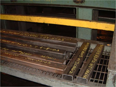
2.3 Fabrication marks not apparent. Courtesy of AISC |
2.3 Fabrication marks (number markings put on the members during the fabrication and erection process) should not be apparent, as the final finish appearance is more critical on these feature elements.
There are different ways that these markings may be made not apparent. In some instances the marks could be left "as is" but located away from view. In other cases they may be lightly ground out. They could also be filled prior to finishing. The treatment of these might vary throughout the project as appropriate by member and location.
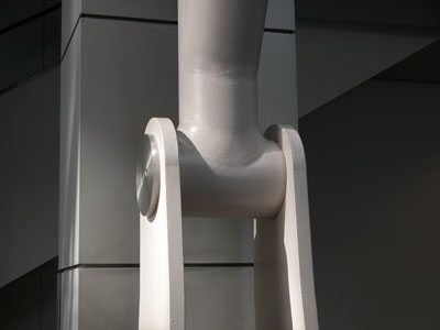
2.4 The welds should be uniform and smooth, indicating a higher level of quality control in the welding process. The quality of the weld appearance is more critical in AESS 2 as the viewing proximity is closer.
Quality welding is more stringent in AESS 2 categories and higher. This is a key characteristic and ensuring good quality welds can save substantial cost in a project. If welds are uniform and consistent in appearance there may be less need for grinding the weld. Too many welded connections are subjected to needless grinding which can add substantial increases to a project budget. Welding is a natural condition of steel connections, and if neatly done, should be able to remain as part of the final product.
 |
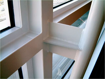 |
2.4 The grinding of these welds incurs a cost premium but is necessary for the seamless look of the connection on this higher level AESS structure. This is not universally necessary, especially considering the viewing distance of AESS 2 elements. This treatment should be saved for AESS 4 Characteristic 4.3 Surfaces filled and sanded, where the elements are in close viewing range and sometimes able to be touched. |
Welds are plainly visible but of good, uniform quality so complementary to the structure. It must be recognized that welding is a technical means to join the pieces and that if the welding is neatly done, it is not necessary to remove the weld material. |
Ultimately this would indicate that more of the welds might be carried out in the fabrication shop to reduce site welding where the conditions may not be optimum. This can impact the design of joints as well as the transportation of potentially larger pre-assemblies and the erection on site. This does not infer that high quality site welding is not possible, only that it might incur a cost premium over shop welding.
