Innovative Connections
Taking the Next Steps from Basic Connections
Everything starts with basic connections. Regardless of how complicated a connection might appear in the end, all connections make use of the basic methods for creating connections and joining steel as their starting points.
ARCHITECTURALLY EXPOSED STRUCTURAL STEEL: PART THREE
Connections
Sponsored by the American Collegiate Schools of Architecture (ACSA)
A good way to begin to design your own more complicated looking connections is to start by understanding:
INITIALLY...
• What sort of load paths are going through the connection?
• Are the members in tension or compression?
• Does the connection need to use a development of a basic lap joint?
• Does the connection need to use a development of a butt joint - ie. does an aspect of the connection need to be "in line"?
• Is the connection based on a type of beam to beam connection?
• Is the connection based on a type of column to column extension?
AND THEN FABRICATION AND ERECTION IMPACTS...
• Are any of the connections the result of transportation size limits?
• How does the erection process impact the design of the connection?
• Is the connection fully fabricated in the shop?
• Is the connection dependent on site processes?
• Is welding the dominant connection method?
• Is bolting the dominant connection method?
AND FROM A DESIGN PERSPECTIVE...
• What sort of structural shapes are being connected?
• What is the AESS category, if exposed?
• What sort of fire protection is required?
• What is the finish on the connection?
 |
 |
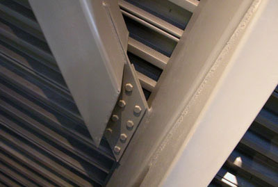
The primary method of attachment of these two members is a simple lap joint. The plate that attaches to the inclined member on the right is connected using a simple fillet weld. The plate that is used to attach the member on the left has been set into the HSS, which looks unique due to the sloped end cut. Again simple fillet welds are used to secure the plate. This is a hinge type connection, so no bending or moment is being transferred through the joint. Likely AESS3. |
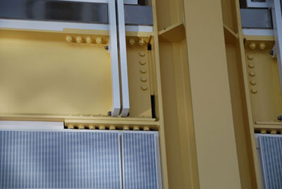
This is a flange-plated moment connection to the column. As such, it is transferring shear through the 5 bolt shear tab and the flange plates are transferring the design moment. The flange plates are the principal connection here rather than reinforcement for the apparently lightly loaded shear tab. This is a cruciform column, with the plates in the column being continuity plates (transverse stiffener plates) that provide continuity for the moment transfer across the column. They have to align with the beam flanges as closely as possible to maintain the load path and prevent failing the column flanges in bending. The welds are all fillet welds, neatly done. The bolts are nicely arranged, taking care to orient/locate the heads consistently. The plates in the column are made to align with the plates that attach to the beam The floor loads on the beams are being transferred to the columns, so only shear forces in play at the connection. Likely AESS3. |