Innovative Connections
Tensile Connections
Architecture that featured elaborate use of tension members as a focus of the design parti did not truly appear until the emergence of the High Tech Movement in the 1970s. The exposed steel systems associated with the style tended to be very lightweight and largely comprised of “assembled” hinge or pin type connections. X bracing was used in lieu of concrete shear walls. The type of "member" that is used in conjunction with a tension based system is normally quite different than for systems designed to take compression or bending forces. These systems will normally use rods or cables. These slender members can be used very well to architecturally highlight this tensile function of the member - as well as use the correct amount of material to resist the forces.
TENSILE SYSTEMS
Sponsored by the American Collegiate Schools of Architecture (ACSA)
Force differentiated structural systems - ones that use light members for tension and heavier members for compression, can provide architectural interest to the design. Force differentiated structural systems employ an integrated approach to the analysis of the structural systems in order to determine the members that can take advantage of the lightness of rods or cables. This application is most easily applied to trusses where the members are normally designed for axial loads, so there is certainty in the designation of the tension members. We know that in most situations that the bottom chord of a simply supported truss acts in tension. The member selected for the bottom chord need not respond to compression forces and so slender member types such as rods can be used instead of HSS or W shapes as is more normally the case. These slender round members, such as rods and cables, that are designed to take tensile loads, need completely different methods of attachment than do structural members.
 |
 |
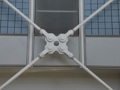
This connection on the Pompidou Centre in Paris that was designed by Piano and Rogers highlights early High Tech detailing for tension connections that is still relevent today. The simple clevis connectors attach to the plate ring. The middle is cut out as a detail and not for structural reasons. The heavier round HSS strut that carries the force back into the building is obviously acting in compression as its size reflects - compared to the lighter tension members that are using rods to carry their loads. |
This tension system as the AEPGBC Headquarters in Vancouver, BC that was designed by Peter Busby, uses force differentiation to select its members. The vertical posts are of a heavier round tubular material in contrast to the much lighter tension members. |
Tension ConnectorsSpecialized connections are often required when attaching tensile members to an exposed steel system. These can be custom designed and fabricated to match the architectural language of the project, or they can be selected from off the shelf sources. There are four primary areas of consideration when designing tension connectors.
• Recognition that this is normally a “pin” type connection, so transfers no moment.
• That the rods or cables are normally quite small in diameter and must be securely fastened to resist pull out due to tension.
• That the type of connector will vary as a function of the use of a cable or rod (rods can be machined to have threads where cables cannot)
• That these systems are normally installed “loose” and must be able to be tightened in order to secure, tension, and plumb the systems.
Many tension connectors are now made from cast steel and mass prefabricated as the demand is quite high. It is advisable, if wishing to keep the project cost down, to check with manufacturers for availability as these products can easily be incorporated into the design. Tension connections come in basic types:
• end connectors, that must be designed to attach the very thin rod or cable to the larger structural members of the system, and
• intermediary connectors that are "within" the rod or cable and must permit tightening of the system
• combined end connectors that also allow for tightening and negate the need for an intermediate tightening connection
 |
 |
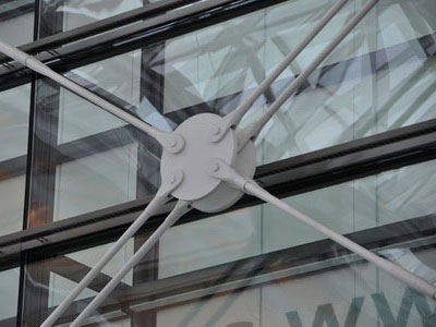
Cross bracing is often done with tensile members as these members need only to act in tension and so can be very thin. The X brace serves to triangulate a rectangular frame, and so only one of the diagonals is ever in tension - the other one is relaxed. |
Different design strategies are applied to the joining of the thin tensile members where they connect at the centre of the brace. Often a clevis attachment is used for this purpose. |
 |
 |
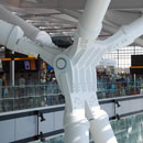
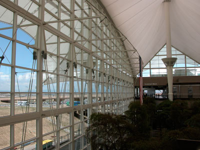
This large end wall at the Denver International Airport uses a tension truss system to provide wind stability. |
Tensile systems allow for clear differentiation of the forces in the members. Here the slightly thicker members are seen to be in compression. |
 |
 |
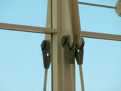
The use of clevis attachments allows for rotation during erection and loading. |
Clevises are attached with cotter pins through plates at the end of the connection at the Denver Airport. |
 |
 |
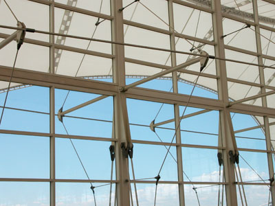
The Denver Airport creates a family of tension details that create consistency in the design. |
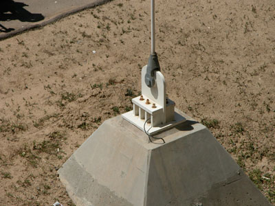
This tie down is securely grounded in a large concrete footing to resist the upload wind forces on the canopy extension of the airport roof. |
 |
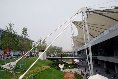 |
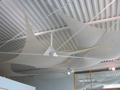
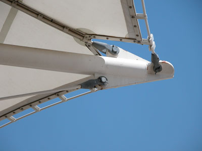
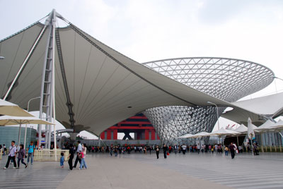
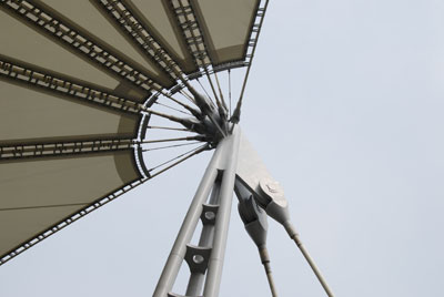
The fabric canopy roof at the Shanghai Expo entry pavilion combines tension systems with a lattice grid system. |
The fabric roof must be securely tied back to the adjacent ground to keep its form and resist uplift forces. You can see the tubular steel mast is much heavier as it is in compression. |
 |
 |
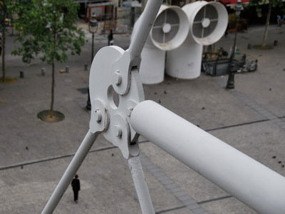
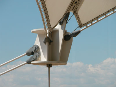
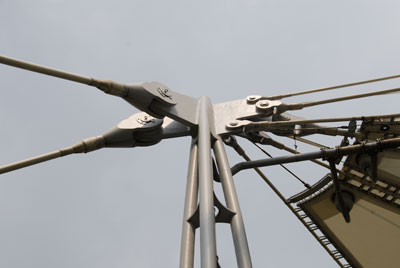
The resolution and attachment of the tension members to the top of the mast is an important geometric problem to resolve. |
There must be enough physical room to create the attachments and allow for the ironworkers to weld the plates to the mast. |
 |
 |
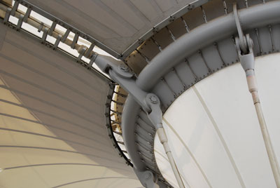
The fabric system for the Shanghai Expo roof must have its edges steel reinforced to provide a secure attachment to the cables. |
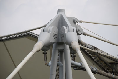
The geometry again is important to resolve in terms of ensuring that the multiple attaching plates can be physically connected to the top of the mast. |