Innovative Connections
Hinge and Pin Connections
Hinges and pins are about transferring shear forces. Hinge and pin connections are some of the simplest steel to steel connections that we find. They are often very lightweight in appearance. They do not have extra steel in the connection to reinforce the connection for any other purpose that providing material to resist shear forces. They are not intended to be able to resist bending moments or rotation, and are sometimes designed TO accommodate a certain degree of rotation. This might be so that the joint moves like an actual door hinge, or so that the joint can accept some degree of rotation as a function of the erection process.
Hinges and pins are often bolted. Although we can transfer shear through a welded connection, many hinge and pin connections will make use of bolts to connect the members.
The difference between a hinge and a pin connection. The difference lies in the number of bolts that we usually find in the connection which in turn infers the ability of the connection to rotate. A pin connection needs to be able to rotate, so it will only be able to have a single bolt to provide the material for the shear transfer. A hinge connection will have a greater number of bolts in order to resist the shear forces. It will not be able to rotate as a result of the bolts, but it is still not intended to resist any bending moment.
 |
 |
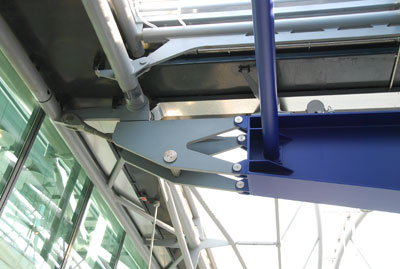
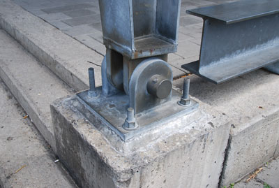
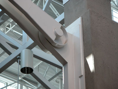
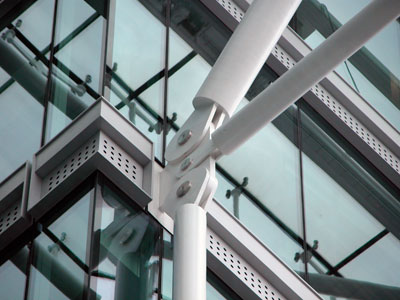
The connection of the grey plate to the blue beam constitutes a hinge connection. It is essentially using bolting to transfer vertical and horizontal forces through the connection. Close examination shows that the bolts go through lapped type connections. |
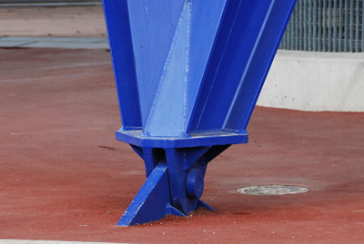
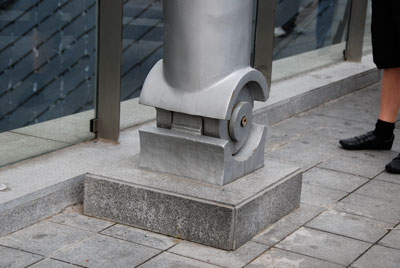
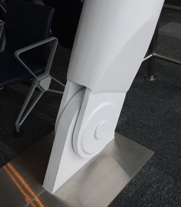
This base connection is a pin connection. It has only one bolt going through a lapped type connection, therefore it can permit rotation. As used it does not rotate, but this would have been a benefit during erection. It still will only transfer vertical and horizontal forces through the bolt. |
Pin Connections
A pin connection works essentially like a lapped joint. It transfers vertical and horizontal shear loads and cannot resist any bending or moment (rotational) forces. The amount of load to be transferred through the joint will determine the size of the bolt and the plate thickness. The diameter of the bolt must be large enough to have enough cross sectional area to handle the shear force. The thickness of the plate must be adequate, when combined with the bolt diameter, to resist pull through.
Many pin connections might look like they are designed to rotate but do not actually function as points of rotation for the structure. Often this type of connection is used to simplify erection by allowing for some slight differences in angles of the members. If the connection need not be stiff, it makes it fairly easy for the ironworkers to slip in the element. The clear function of these type of connections makes them pretty simple and fun to design as you can see from the variety of instances pictured below!
 |
 |
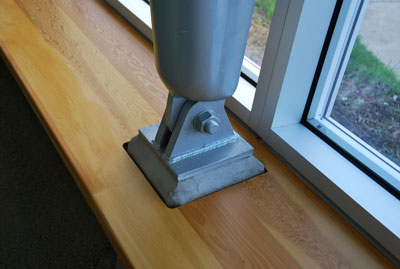
This base connection for a support column at Calgary Water uses a pin connection. A single bolt carries the load. The base plate was attached to the concrete base support prior to installation of the vertical member. Concrete grout covers the space between the base plate of the connection and the steel plate that was cast into the concrete. The space covered by the grout usually contains threaded rods with leveling nuts used to plumb the job prior to attachment of the column member. |
This base connection is a pin connection. It has only one bolt going through a lapped type connection, but in this case the vertical member uses two plates rather than one as can be seen in the example immediately to the left. The two plates simply distribute the vertical load between the plates. The method of attachement to the foundation is pretty evident with the expression of the threaded rods. Trimming all to the same height might have improved the appearance. |
 |
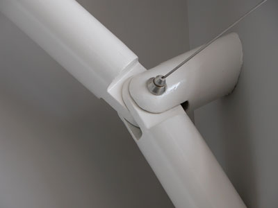 |
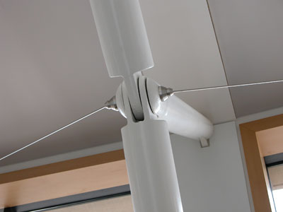
This pin connection is part of a bracing system on the interior of the Salt Lake City Public Library designed by Moshe Safdie. The workmanship on the detail is exquisite. The slight rounding of the edges takes this from a very simple connection to a feature part of the AESS language for the building. |
The filling and grinding of the welds for this brace will have added to the cost of the project. The pin variation here takes us from two to three members joining at one point. Member thicknesses and the plate thicknesses at the point of the pin need to be carefully calculated so that both the geometry and structural capacity of the steel work. |
 |
 |
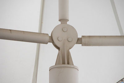
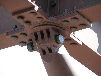
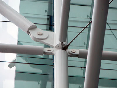
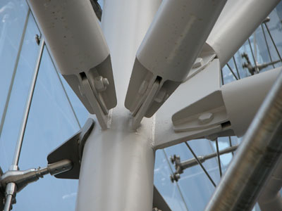
This variation on the pin allows for three incoming members at the meeting of the base connection.Tubes with "lollipop" shaped plates welded to the ends provide for a hidden attachment between the primary round connecting plate set. The rounded ends hidden on the interior of the connection are designed to be able to rotate and not conflict with each other during erection. |
The idea of rotation, even though the connections are seldom expected to rotate in service, can form the basis for aesthetic choices. This base connection for a very tall column at the Shanghai Expo does just that. The rounded element that is added to the column as well as the cup shaped element at the base lead to the impression of movement. |
 |
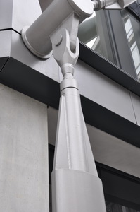 |
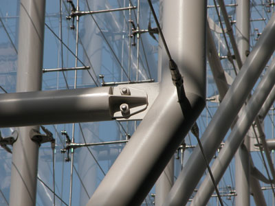
This bracing system is created using elliptical tubes. An innovative end extension has been designed to create the interface between the tube and the round HSS "post" that provides the attachment to the primary structure. In this cast the elliptical tubes have been oriented with their wide dimension in line with the building to make the exterior bracing system appear slimmer. |
The special attachment has been created from a round HSS member with triangular plate "fins" on the sides. This has in turn be welded to a fairly straightforward clevis type connector. |
Fabricating a pin. Many pin connections are relatively simple to fabricate. Plates with holes are welded to the bottom of the structural member. In other instances it is desirable to have the end of the member taper or take on a different geometry in order to make its appearance work better with the overall aesthetics for the project.
 |
 |
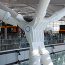
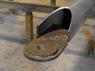
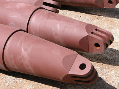
The fabrication for the many pin connections at Pearson International Airport were fabricated in this fashion. The ends of the round HSS members were cut on an angle. Plates will be cut and welded in place to complete the angle. The special fabricated pin connecting plates were created. The additional donut of steel on the plate to thicken the steel there to resist forces at the connection, but the design to hold the material back from the edge to create a nice looking detail. The welds were carefully done. |
The finished piece looks very elegant in situ. The taper on the column end adds greatly to the appearance of the member. A blunt end would have been substantially less expensive but detracted from the look of the member. |
WHERE SLIGHT MODIFICATIONS IN THE ERECTION AND INSTALLATION OF THE PINS WORKS WITH GEOMETRY...
 |
 |
The ends of the branches of the supporting tree at the University of Guelph Science Building Atrium, fabricated by Walters Inc., were created in a similar fashion to those for Pearson Airport above, also by the same fabricator. As this is AESS4 steel, the lines are very crisp. The members are also to receive a high gloss painted finish. |
The ends of the branches of the tree will be inserted into this pin connection. Tolerances are tight enough to be one half standard for the AESS application, but must still allow for the ends to meet without too much force. The lower end of the branch will be welded into a cast node and there is not much forgiveness in that half of the erection of the member. It has to happen at the pin. |
 |
 |
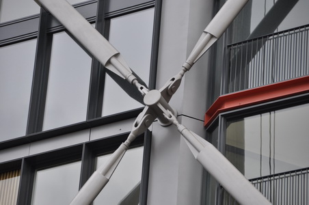
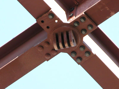
The X plates that form part of the pin connection mount are attached to the beams at the fabricator's shop. The round element will be welded on site as each of the connectors must adapt a slightly different angle of entry as a result of the asymmetry of the tree like members. |
Two types of bolts are used on the connector. TC bolts are used to attach the X plate to the beams. These are chosen for their clean profile. A larger high strength steel bolt with a hex head is used in the connector. We can see that multiple shear planes are developed on this bolt as a result of the large number of plates. Essentially this is a lapped joint. |
 |
 |
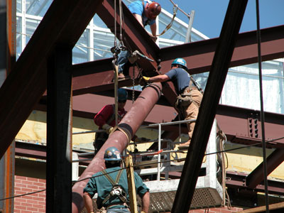
This is the last tree branch being erected. It is desired that the slots of the branch slide without much force into the pin above as the AESS finish on the steel will not permit the ironworks to force the member as they would damage the finish. |
As can be seen from this image, all of the tree branches meet their pins at slightly different angles. The welding of the round pin plates on site allowed for dimensions and angles to be carefully verified prior to welding. |
Pin Connected Trusses. When we look at the forces in trusses we consider that only pure axial forces of tension or compression act in the members. They are connected by "pins" that in theory would allow for free rotation of the joints. Assemblages of trusses using true pin connections can work in two and three dimensions.
 |
 |
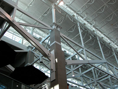
The trusses at Denver International Airport incorporate some true pin connections. In theory trusses are designed with pin connections, but most are not actually fabricated that way. The trusses use a combination of parallel and single members to create the situations of overlap to allow for the pin type joints. |
The pin connection uses a lapped joint and the bolt is put through a situation of double shear. The thickness of the plate that attaches to the column is designed to match the thickness of the members of the truss in order to carry through the overlapping geometry of assembly that is key to the design. |
 |
 |
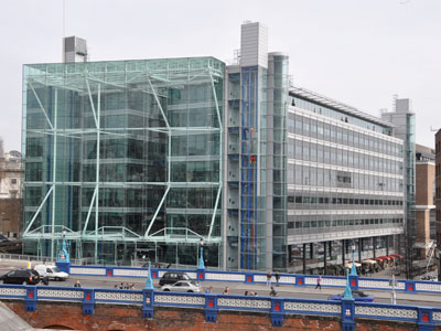
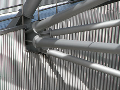
Tower Bridge House in London, England by Richard Rogers uses pin connections to create a dynamic looking exposed steel structure to support the glazing for the large entry atrium. |
A consistent language of connections uses rounded plates that have been welded to either round or rectangular HSS members. Stainless bolt fasteners make for a clean appearance in conjunction with the white painted steel. |
 |
 |
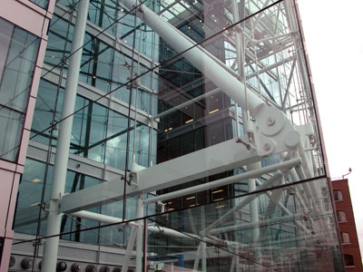
Simple pin connections using two plates for the attaching member and one at the column are typical for all connections. The plates vary in size in accordance with the members, which are sized according to the loads that they carry. |
Where the trusses attach to the building a large plate has been designed to accommodate three incoming elements. |
Hinge Connections
Hinge connections is a rather large category of framed connections that includes many types that are either not intended to rotate or are not designed to resist rotation. Vertical and horizontal forces are transferred through these joints.
 |
 |
These connections at the Rose Center in New York City by Ennead Architects are bolted hinge type connections. They use more than one bolt to fix the connection. They will transfer vertical and horizontal forces and are not intended to resist bending moments. Simple lap joints and fillet welds are used to connect the pieces. |
This connection at the Rose Center uses similar strategies to keep a consistency of language. The angled join in the truss is accomplished by a welded connection to make the structure more clear. The welding would be done in the fabrication shop and the web elements of the trusses that are bolted would be erected on site. |
 |
 |
The back face of the support system of the Pritzker Pavilion in Chicago, Illinois designed by Frank Gehry, uses a combination of bolted and welded connections that act as hinge connections in that they are not designed to resist rotational forces. Here the geometry of the assemblage acts to create stiffness in the structure. |
The connections on the Pritzker Pavilion use both welded and bolted methods. The more complicated welded connections would be done in the shop. The overall steel project has been broken into larger assemblages based on their shipping size. The erection of the steel system would also contribute to decisions as to the placement of bolted versus welded connections. |
 |
 |
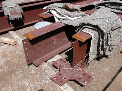
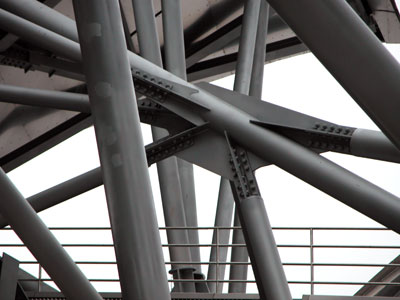
The large plate into which the round HSS members are joined creates a dynamic look to this hinge connected piece. The methods of attachment are simple bolted connections using primarily lap type joints. They are similar in construction to those at the Rose Center in that a plate has been welded to the end of the round HSS tube to close it and the connecting plates welded to the end of the closed tube. |
Some of the elements of the Pritzker Pavilion are site welded. It was important to the overall aesthetic of the project to differentiate the look of these attachments from those directly behind and supporting the curved panels of the bandshell. Regardless, they still act as hinge connections as they are not intended to resiste bending. |
 |
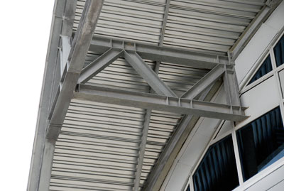 |
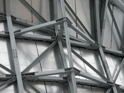
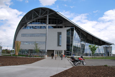
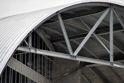
Calgary Water, in Calgary, Alberta, designed by Manasc Isaac Architects uses galvanized steel to create this sustainable LEED building. The geometry and curves of the facility help to make the shape rigid. This allows for the use of hinge connections throughout the elements of the frame of the building. |
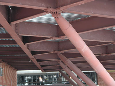
These trusses are fabricated from wide flange sections to provide an industrial look. Although the connections are all welded, trusses are designed to accommodate axial loads so the joints or panel points in the truss act as hinges in that they transfer only horizontal or vertical loads. |
 |
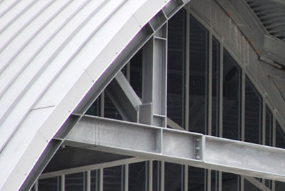 |
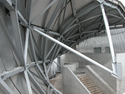
The end trusses at Calgary Water use wide flange sections. The connection points of the members of the truss act as hinge connections. Web stiffeners have been used at the panel points to assist with load transfer. |
A closer examination of the large end truss of the building reveals a bolted connection. It is barely visible so appears as a welded connection from a distance to be consistent with the language of the building. It is ther to allow for an easy site connection of the large truss element to the rest of the structure. |